
SoW, PRD &
Architecture
Phase
Scope of Work Finalization
Product Requirement Document
A BoM Finalization
Architecture Document

Schematic
Design
Phase
Power Budget Analysis
GPIO Pin Mapping
Schematic Library Creation
Schematic Drafting
BoM Creation & Finalization

Layout
Design
Phase
Footprint Creation
Get the PCB Stack Up
Layout Design
Gerber Release
PCB Fabrication & SMT Assembly

Bring up
& Product
Delivery Phase
Test Cases Preparation & Finalization
PCBA Bring Up EDVT Report
QA/QC Testing
Final Delivery of Product
Architectures
- Qualcomm
- Synaptics
- NXP Semiconductor
- Nordic Semiconductor
- Quectel
- Macronix
- Micron
- Winbond Electronics
- KIOXIA America Inc.
- Analog Devices/Maxim Integrated
- ST Microelectronics
- OSRAM
- Panasonic
- Texas Instruments
- TDK Corporation
- Microchip Technology
- Renesas
- TE Connectivity
- AMP Connectors
- Molex
- Hirose Electric Co Ltd
- Samtec
Schematic Design
- High Speed Digital Board Designs
- Low Speed Digital Board Designs
- RF and Wireless Design Solutions
- MCU Designs
- Power-optimized & Battery Operated Designs
- Development Platforms
- System-on-Modules (SoM)
- Embedded Processor Based Designs
- Analog and Audio Circuit Designs
- Design Estimations/ BOM Optimization
- ADCs and DACs
- Allegro, OrCAD, Altium, Ki-CAD
Layout Design
- Library Management
- Small Footprints
- PCB Stack Up Design
- Board Size and Net Count
- Signal Integrity
- Power Integrity
- Thermal Analysis
- Power Distribution
- Component Clearance and Mechanical Constraints
- EMI and EMC
- Design for Manufacturing (DFM) Analysis
- Design for Assembly (DFA) Analysis
- Design for Testing (DFT) Analysis
- Design Rules and Constraints
- Allegro, OrCAD, Altium, Ki-CAD
Interfaces
- MIPI CSI & DSI, LVDS
- Ethernet SGMII & RGMII
- Ethernet PHY USB
- PCI Express, HDMI, CAN, SATA
- GPS, GSM, WiFi, Bluetooth, LTE, NFC
- AMIC, DMIC, SoundWire, SLIMbus Digital Audio
- LDDDR3ILPDDR4ILPDDR4X /LPDDR5
- DDR2IDDR3IDDR4 SDRAM
- SDIO, SDC, eMMC/UFS, eMCP
- Touch Screen
- Sensors I2C, SPI, UART
Others
- Prototype to Production Ownership
- Prototype Development
- Manufacturing Support
- Mechanical/Enclosure Designing for Products
- Design Estimation Optimization
- Supply Chain Management
- Quality Assurance
Teksun Hardware Process 14 Steps
- Product Requirement Specification Phase
- Finalizing requirements in an embedded project is an important step in ensuring the successful development and deployment of the system. Here are some key steps and considerations for finalizing requirements in an embedded project:
- Requirement Identification
- Requirement Analysis
- Prioritization and Classification
- Requirement Traceability
- Requirement Validation
- Requirement Documentation
- Change Management
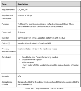
- We follow PRD (product requirement document) document that cover all aspect of requirements mentioned above.
- We define use case, Product Design Approach, Product Development Lifecycle – Teksun Process, Teksun scope of work,Out of Scope, Major Component Overview, block diagram,
- It also cover Functional Requirement that include
- Requirement Description with requirement ID, purpose, input ,output, Constraint, Acceptance criteria
- PRD also includes standards ,statutory and regulatory, Special usage requirements, assumptions , gray areas , acceptance criteria,risk analysis , open items, and external reference.
- Remember, finalizing requirements is not a one-time activity but an ongoing process. Regularly revisit and reassess requirements as the project progresses to ensure that they remain aligned with the project goals and stakeholders’ expectations.
- Architecture Phase
- Product Specification
- Hardware Architecture
- Hardware Design Limitation
- Overall BOM Cost
- Major Component Selection
- Technical Stack
- Assumption
- Gray Areas
- Acceptance Criteria
- Risk Factors And Mitigation Plan
- Block diagram
- Pin Mapping
- Power Budgeting
- FMEA (Failure Modes and Effects Analysis)
- When selecting major components for an embedded project, there are several criteria to consider.The specific criteria may vary depending on the nature of the project,but here are some common factors to evaluate:
- Functional Requirements
- Performance
- Quality and Reliability
- Availability and Longevity
- Cost
- Compatibility and Interoperability
- Development and Support:
- Scalability and Flexibility
- Power Efficiency
- Safety and Compliance
- By carefully evaluating these criteria and conducting thorough research, you can select major components that align with the project’s requirements, budget, and long-term objectives.
- Major Component selection sheet Example
- When creating a schematic design for an embedded project, there are several criteria to consider. The schematic design is a crucial step in defining the electrical and functional aspects of the system. Here are some key criteria to keep in mind:
- When selecting major components for an embedded project, there are several criteria to consider. The specific criteria may vary depending on the nature of the project, but here are some common factors to evaluate:
- System Requirements
- Component Selection
- Signal Integrity
- Power Distribution
- EMI/EMC Considerations
- Documentation and Clarity
- Revision Control
- Collaboration and Feedback
- By considering these criteria, you can create a well-designed schematic that effectively represents the electrical aspects of your embedded project and serves as a solid foundation for further development and implementation.
- Schematic Review checklist link Here
- When creating a Bill of Materials (BOM) for an embedded project, it is important to consider several criteria to ensure accuracy, completeness, and efficiency. The BOM provides a comprehensive list of all components required for the project, including part numbers, quantities, and other relevant details. Here are some key criteria to keep in mind when creating a BOM:
- Component Information
- Quantity and Units
- Supplier and Pricing Information
- Manufacturer and Distributor Support
- Alternatives and Second Sources
- Lifecycle and Obsolescence Management
- BOM Version Control
- By considering these criteria, you can create a well-designed schematic that effectively represents the electrical aspects of your embedded project and serves as a solid foundation for further development and implementation.
- BOM Review checklist Here
- Component placement plays a crucial role in the overall performance, reliability, and manufacturability of an embedded system. When considering component placement in a PCB (Printed Circuit Board) design, here are some key criteria to keep in mind:
- When designing footprints for components in a PCB layout, it is important to consider several criteria to ensure accurate and reliable soldering, proper component alignment, and optimal electrical performance. Here are some key criteria to keep in mind when designing footprints:
- Component Datasheets
- IPC Standards
- Component Geometry
- Pad Design
- Solder Mask and Paste Mask
- Keep-out Zones
- Thermal Considerations
- Silkscreen and Reference Designators
- Manufacturing Constraints
- Verification and Validation
- Documentation
- By considering these criteria during footprint design, you can create accurate and reliable footprints that ensure proper soldering, optimal electrical performance, and seamless integration of components into the PCB layout.
- Footprint Review checklist Here
-
- Component placement plays a crucial role in the overall performance, reliability, and manufacturability of an embedded system. When considering component placement in a PCB (Printed Circuit Board) design, here are some key criteria to keep in mind:
- When designing footprints for components in a PCB layout, it is important to consider several criteria to ensure accurate and reliable soldering, proper component alignment, and optimal electrical performance. Here are some key criteria to keep in mind when designing footprints:
- Signal Integrity
- Thermal Management
- Power Distribution
- Component Clearance and Mechanical Constraints
- Electromagnetic Compatibility (EMC)
- Manufacturing and Assembly
- Design for Testing (DFT)
- Documentation and Clarity
- Design Rules and Constraints
- Iterative Optimization
- By considering these criteria, you can create an optimized component placement that enhances the functionality, performance, and manufacturability of the embedded system while ensuring good signal integrity, thermal management, and compliance with design and assembly requirements.
- Component Placement review Checklist Here
- Electro-mechanical verification is an important process to ensure that the electrical and mechanical aspects of a product or system are properly integrated and function as intended. Here are some criteria to consider when performing electro-mechanical verification:
- Dimensional Compatibility
- Mechanical Stress and Strain
- Electrical Connection
- Electrical Grounding
- EMI/EMC Compliance
- Thermal Management
- Mechanical and Electrical Safety
- Functional Integration
- Environmental Durability
- Documentation and Standards Compliance
- By considering these criteria during the electro-mechanical verification process, you can ensure that the electrical and mechanical aspects of your product or system are thoroughly evaluated and meet the required performance, safety, and reliability standards.
- Mechanical Design Checklist Here
- When designing a PCB layout, there are several important criteria to consider to ensure the functionality, performance, manufacturability, and reliability of the printed circuit board. Here are some key criteria to keep in mind:
- Component Placement
- Signal Integrity
- Power and Ground Planes Incorporate
- Routing and Trace Considerations
- Thermal Management
- Design for Manufacturing (DFM)
- Design for Testing (DFT)
- EMI/EMC Considerations
- Component and Footprint Selection
- Documentation and Verification
- Revision Control
- By considering these criteria during the PCB layout design process, you can create a well-optimized layout that meets the project requirements, complies with industry standards, and can be efficiently manufactured and tested.
- By considering these criteria during the electro-mechanical verification process, you can ensure that the electrical and mechanical aspects of your product or system are thoroughly evaluated and meet the required performance, safety, and reliability standards.
- PCB Layout review Checklist Here
- The criteria for PCB board bringup typically include the following aspects:
- Power Supply
- Component Placement
- Solder Joints
- Signal Integrity
- Clock and Timing
- Power Integrity
- Functional Testing
- Thermal Management
- Compliance and Standards
- Board bring up Checklist Here
- Board bringup report sample Checklist Here
- The criteria for hardware-firmware integration, specifically when it comes to integrating firmware (also known as “dump code”) with hardware, typically involve the following considerations:
- The criteria for PCB board bringup typically include the following aspects:
- Firmware Compatibility
- Hardware Initialization
- Communication Interfaces
- Register Configuration
- Peripheral Integration
- Memory Management
- Error Handling and Fault Tolerance
- Real-Time Constraints
- Integration Testing
- The criteria for Quality Assurance (QA) and Quality Control (QC) testing typically involve the following considerations:
- Test Planning
- Functional Testing
- Performance Testing
- Usability Testing
- Compatibility Testing
- Security Testing
- Regression Testing
- Stress and Load Testing
- Error Handling and Exception Testing
- Compliance Testing
- Documentation Review
- Bug Tracking and Reporting
- Continuous Improvement
- The goal of QA/QC testing is to ensure the quality, reliability, and functionality of the product or system, providing confidence to stakeholders and end-users that it meets their expectations and requirements.
- QA/QC Checklist Here
- Final testing criteria encompass a set of considerations to ensure that the product or system is thoroughly evaluated before its release or deployment. These criteria may include:
- System Integration Testing
- End-to-End Testing
- User Acceptance Testing (UAT)
- Performance and Scalability Testing
- Security and Penetration Testing
- Compatibility Testing
- Localization and Internationalization Testing
- Accessibility Testing
- Regression Testing
- Reliability and Stability Testing
- Disaster Recovery and Backup Testing
- Compliance and Certification Testing
- Documentation and Release Readiness
- User Feedback Incorporation
- By adhering to these final testing criteria, organizations can ensure that their products or systems are thoroughly evaluated, meeting the desired quality standards, and ready for successful deployment or release to end-users.
- The criteria for shipment and release of a product typically involve the following considerations:
- Quality Assurance
- Regulatory Compliance
- Manufacturing Readiness
- Inventory Management
- Packaging and Labeling
- Documentation and Manuals
- Order Fulfillment
- Logistics and Shipping
- Export and Import Compliance
- Customer Support Readiness
- Warranty and Service Agreements
- Feedback and Continuous Improvement
- By considering these criteria, organizations can ensure a smooth and successful shipment and release process, delivering high-quality products to customers while meeting regulatory requirements and customer expectations.
- The criteria for deployment and support of a product or system typically involve the following considerations:
- Deployment Planning
- Installation and Configuration
- Compatibility and Integration
- User Training
- Data Migration
- System Performance Monitoring
- Technical Support and Helpdesk
- Bug Fixing and Updates
- Documentation and Knowledge Base
- Continuous Monitoring and Improvement
- Security Updates and Vulnerability Management
- Customer Relationship Management
- End-of-Life Planning
- By considering these deployment and support criteria, organizations can effectively deploy their products or systems, provide reliable customer support, and ensure customer satisfaction throughout the product life cycle.
Teksun Hardware Process 14 Steps
![]()
Requirements
finalization
![]()
Major Component
Selection
![]()
Schematic
Design
![]()
BOM
Creation
![]()
Footprint
Design
![]()
Component
Placement
![]()
PCB
Layout
![]()
Board
Bring up
![]()
H/W, F/H
Integration
![]()
QA/QC
Testing
![]()
Final
Testing
![]()
Shipment &
Release
![]()
Electro mechanical
verification
![]()
Deployment
and Support

